Exercise
Introduction
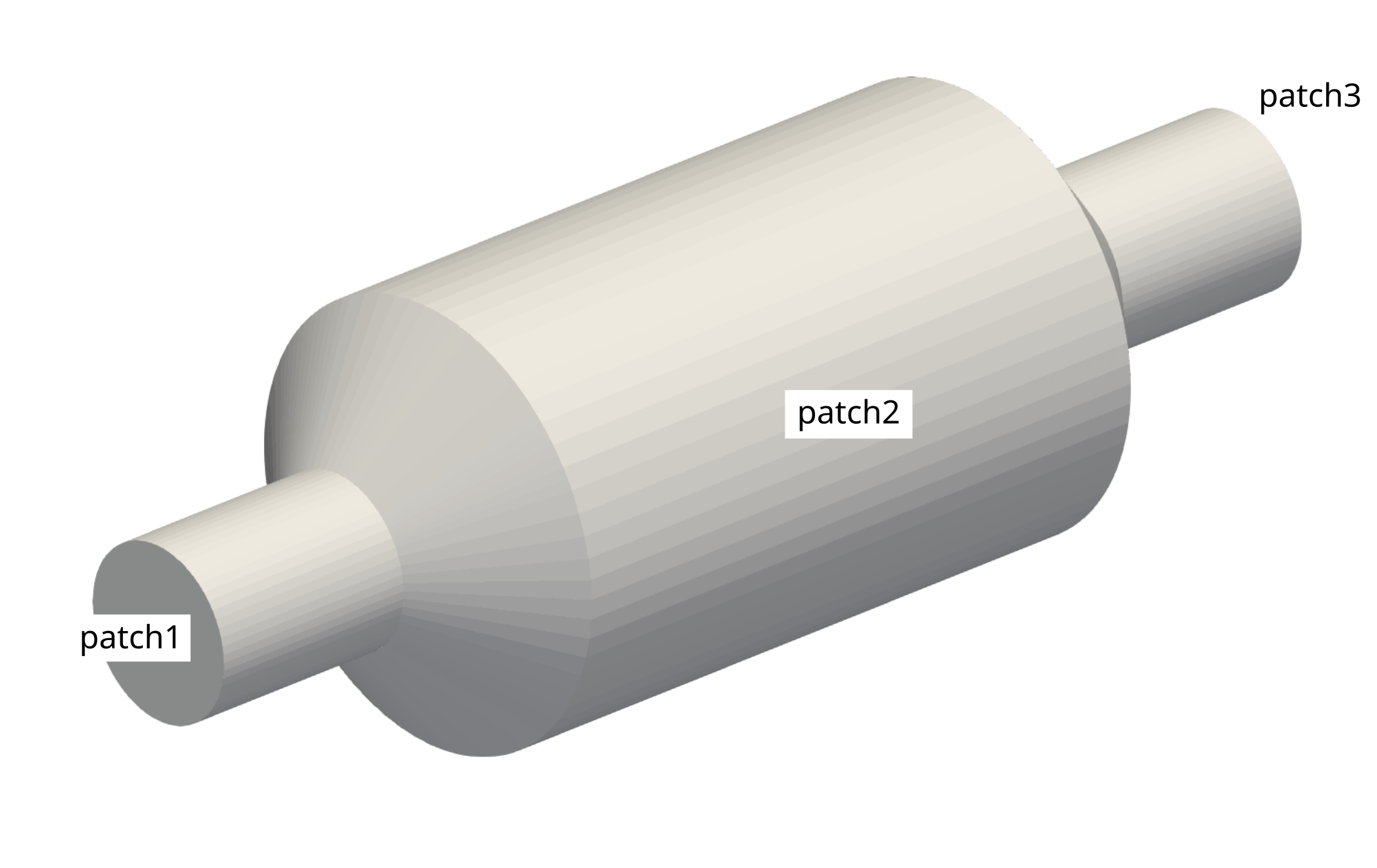
The geometry of a catalytic converter is given (see Figure below). For the simulation of the interior flow a unstructured, hexahedral-dominant mesh should be created.
Navigate with your terminal to the extracted sub-directory 3_catalytic_converter within the 2_mesh_generation directory. This folder only contains the geometry file geometry.obj.
Tasks
- Copy the
systemdirectory from the buildings case to3_catalytic_converter. - Adjust the
meshDictto create an unstructured, hexahedral-dominant mesh meeting the following requirements:- Maximum cell size of 8 mm
- Surface-based refinement at
patch2with a cell size of 2 mm and a refinement thickness of 4 mm - Region-based refinement at the center of the catalytic converter between \(-100 \leq x \leq 100\) with a cell size of 4 mm
- Inflation layers at
patch2with 5 layers and a growth ratio of 1.2 - Rename the patches to
inlet,outletandwallsand set their corresponding types correctly - The total cell count should be around 180,000 - 220,000 cells, which should be varified using
checkMesh.
- Make sure the scaling of the mesh is correct.
- Check the mesh quality and identify regions with elevated non-orthogonality.
- Create two copies the
3_catalytic_converterdirectory named3_catalytic_converter_mediumand3_catalytic_converter_fine. Repeat the mesh generation in these new directories and create a refined medium and fine mesh suitable for a mesh independency study.