Hex-dominant Mesh Generation
Introduction
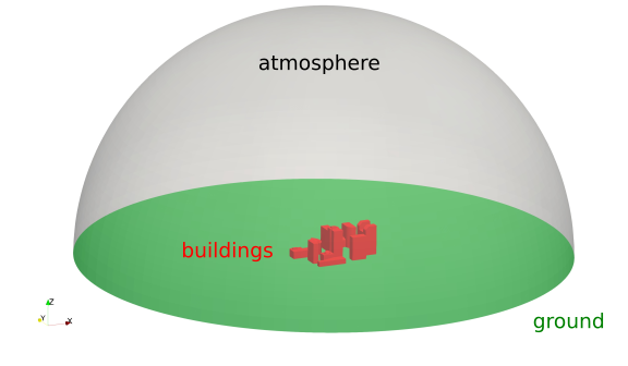
This tutorial explains how the OpenFOAM meshing tool cartesianMesh is used to create unstructured, hexahedral-dominant mesh of a set of buildings. At the end, the mesh will be visualized using ParaView. The geometry of the case with the corresponding patch names looks as follows:
Navigate with your terminal to the extracted sub-directory 2_buildings within the 2_mesh_generation directory.
Case structure
In OpenFOAM, the computational mesh, field data, model properties and numerical model parameters are stored in a set of files within a case directory. The case directory is given a suitably descriptive name, here 2_buildings. This folder contains the following subfolders and files:
2_buildings
├── system
|   ├── controlDict
|   ├── fvSchemes
|   ├── fvSolution
|   └── meshDict
└── geometry.obj

1 directory, 5 files
The relevant files for this tutorial case are:
meshDictin thesystemdirectory: Contains the configuration for the automated meshing process.geometry.obj: The geometry file forming the boundaries of the computational domain.
Automated Mesh Generation
The cartesianMesh utility automatically generates a hexahedral-dominant 3-dimensional mesh from a user-provided surface geometry. Supported surface formats are, among others, Stereolithography (STL) or Wavefront Object (OBJ). The meshing process is as follows:
- A structured background mesh is generated based on a user-defined maximum cell size.
- Local mesh refinement is applied on individual patches or regions within the solution domain (optional).
- The cells are snapped to the provided geometry to form a smooth mesh.
- Inflation layers are introduced on individual patches (optional).
Meshing configuration
The meshing process with cartesianMesh is solely controlled via the meshDict configuration file in the system directory. At the beginning of this tutorial, this file has the following minimal structure:
// * * * * * * * * * * * * * * * * * * * * * * * * * * * * * * * * * * * * * //

surfaceFile "geometry.obj";

maxCellSize 10;
These two settings are at least required for creating a mesh:
surfaceFile: Name of the geometry file in the case folder, heregeometry.objwhich is located in the OpenFOAM case folder.maxCellSize: Maximum cell size in meters for creating the background mesh.
With this minimal example, the unstructured hexahedral-dominant mesh can be created using the following command:
cartesianMesh
Within a few seconds, the mesh is created automatically and stored inside the constant/polyMesh directory. In order to inspect the mesh, start ParaView:
paraFoam &
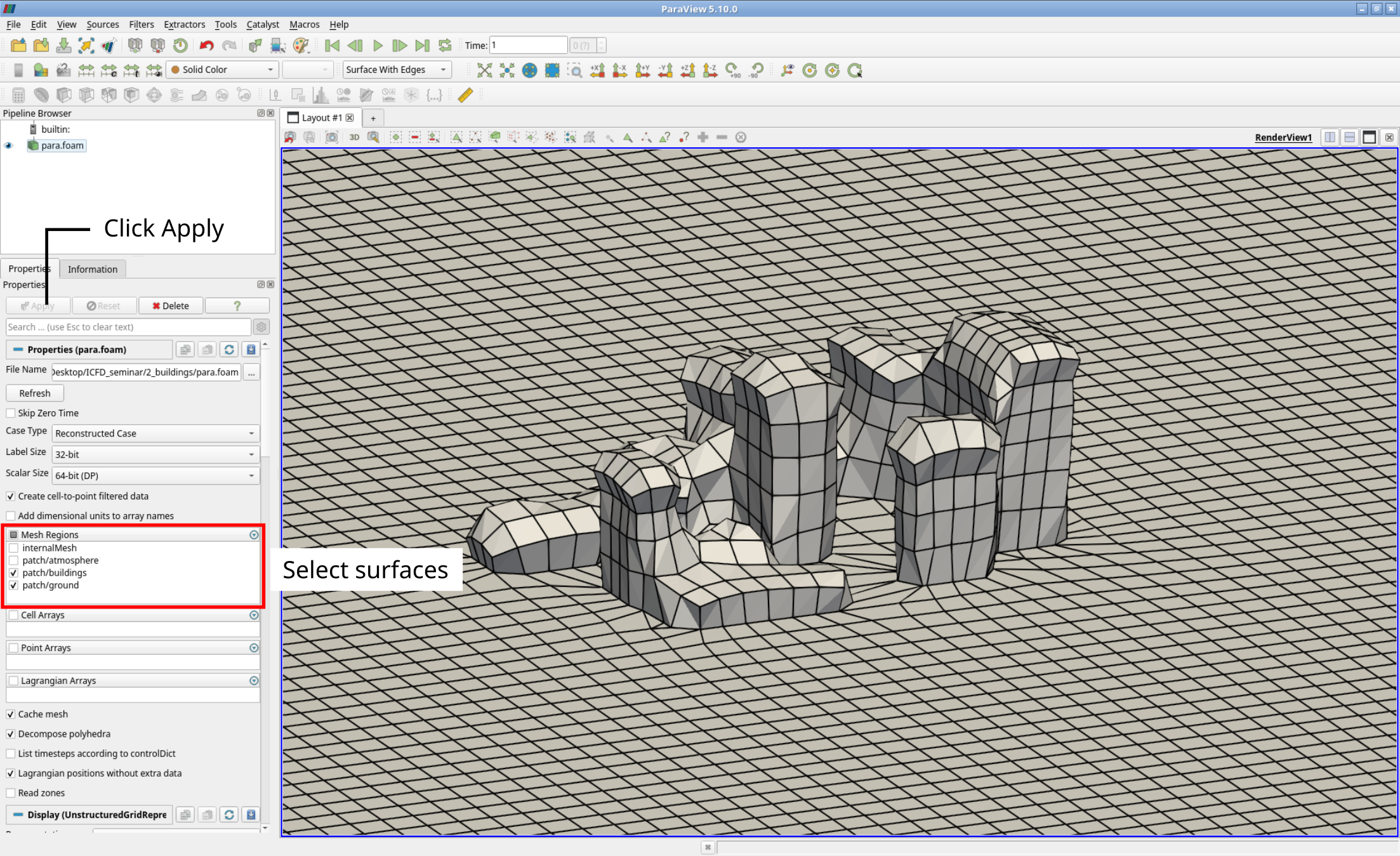
The mesh close to the surface of the buildings can then be visualized by only selecting the buildings and ground patch at the Properties Panel in ParaView:
Surface-based mesh refinement
At this point, the mesh is too coarse to resolve either the geometric features of the buildings nor the flow field in the wake. Reducing the maximum cell size of the backgroud mesh would result in a disproportionately large mesh. Therefore, the mesh is locally refined at the surface of the building. This can be achieved by adding the following lines below the entry maxCellSize to the meshDict:
localRefinement
{
    buildings
    {
        additionalRefinementLevels  2;
        refinementThickness         10;
    }
}
This setting can be summarized as follows:
localRefinementis the keyword forcartesianMeshto apply a surface-based refinement.buildingsis the name of the patch, at which a surface-based refinement should be applied.additionalRefinementLevelsspecifies how often the background mesh at the surface should be refined, e.g., split by two in all three directions in space.refinementThicknessdefines how far the refinement from the surface should reach out into the volume mesh.
It is possible to refine multiple patches at once by adding their respective refinement settings based on patch the name to the
localRefinemententry.
So in this case, the cells at the patch buildings are refined twice (resulting cell size is then \((10\,\text{m})/2^2 = 2.5\,\text{m}\)) and the refinement reaches out 10 meters into the volume mesh. In order to create the new mesh with the updated meshDict, the cartesianMesh utility has to be executed once again:
cartesianMesh
Rerunning the meshing tool
cartesianMeshagain will overwrite the mesh previously stored inconstant/polyMesh!
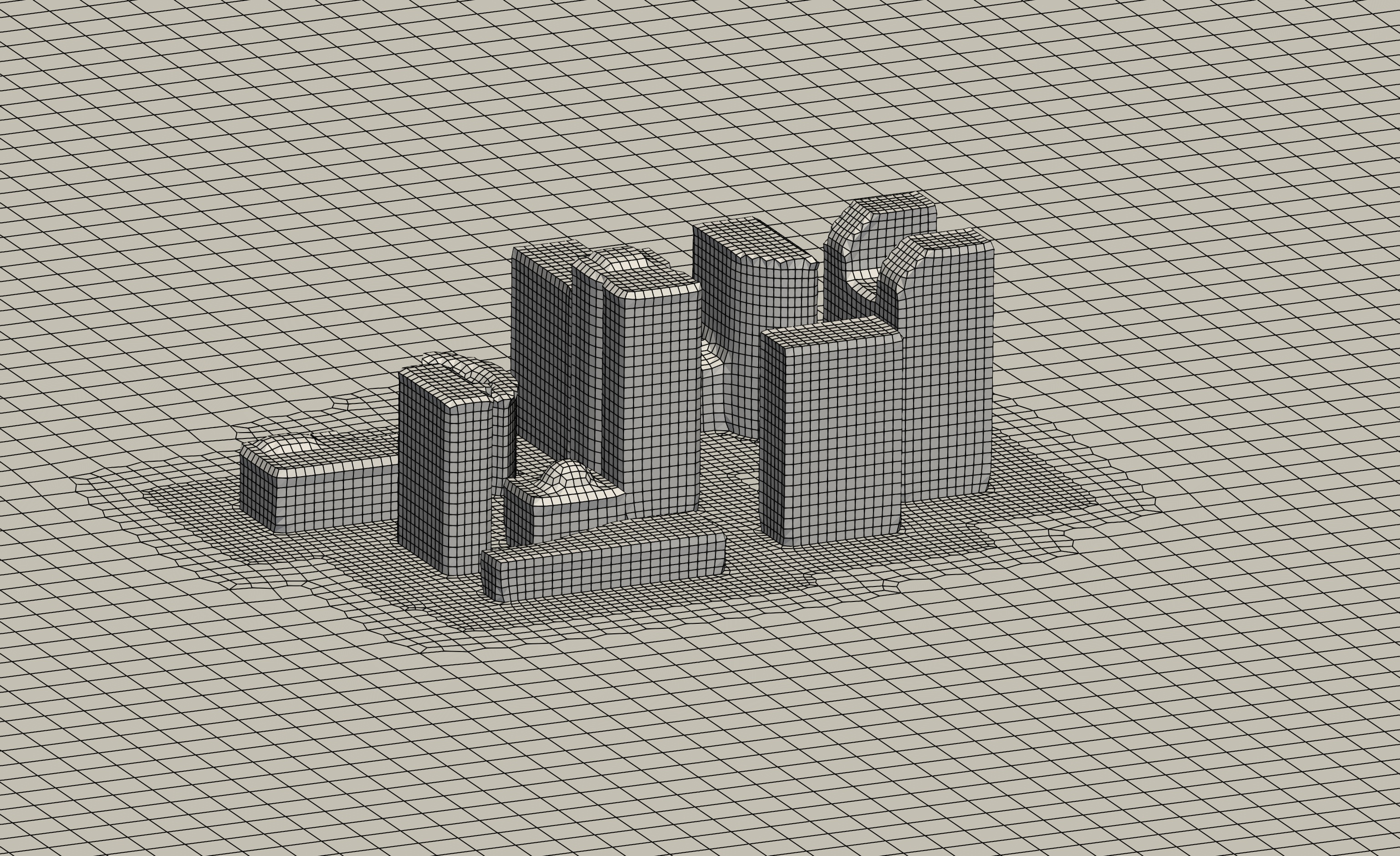
Once the mesh has been recreated, the visualization in ParaView can be updated by clicking the Refresh button the Properties Panel. The following figure shows the resulting surface mesh close to the buildings with a significantly improved resolution:
Region-based mesh refinement
Although the surface-based refinement around the buildings is adequate, the wake of the buildings is still too coarse to resolve the expected flow structures. This issue cannot be resolved by increasing the refinement thickness of the surface-based refinement as this would result in a disproportionately large mesh. Therefore, a refinement region must be defined covering the wake, in which the mesh will also be refined. This can be accomplished by adding the following lines to meshDict below the previous entries:
objectRefinements
{
    wake
    {
        type        box;
        centre      (200 0 0);
        lengthX     400;
        lengthY     150;
        lengthZ     200;
        additionalRefinementLevels    1;
    }
}
This setting can be summarized as follows:
objectRefinementsis the keyword forcartesianMeshto apply a region-based refinement.wakecan be any name for this refinement.typespecifies the shape of the region-based refinment.centerandlengthspecify the center and the dimensions of the refinement box in all three directions in space.additionalRefinementLevelsspecifies how often the background mesh at the surface should be refined, e.g., split by two in all three directions in space.
There are numerous different shape types for refinement, such as cone, sphere, or line.
It is possible to have multiple refinement regions at once by adding their respective refinement settings to the
objectRefinementsentry.
In this case, the refinement region is a box with the center coordinates (200 0 0) and the dimensions of 400 by 150 by 200 meters. The cells within this box are refined once (resulting cell size is then \(10/2^1 = 5\,\text{m}\)). In order to create the new mesh with the updated meshDict, the cartesianMesh utility has to be executed once again:
cartesianMesh
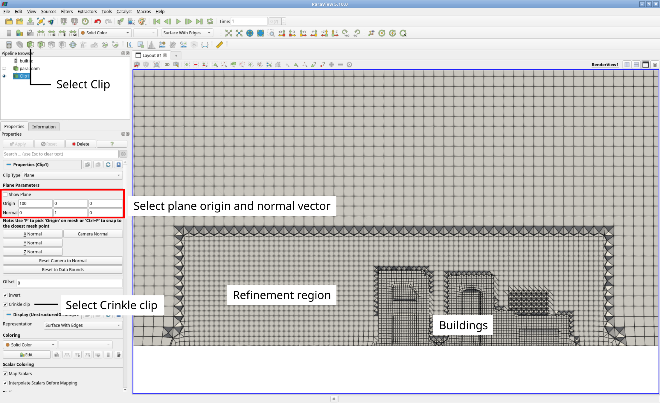
Once the mesh has been recreated, the visualization in ParaView can be updated by clicking the Refresh button the Properties Panel. In order to show wake region, select the internalMesh in the Properties Panel, and then the Clip filter with a center of origin of (200 0 0) with a normal vector of (0 1 0). Selecting Crinkle clip completely shows all intersected cells. The following figure shows the resulting clp through the volume mesh with the refinement region on the left of the buildings:
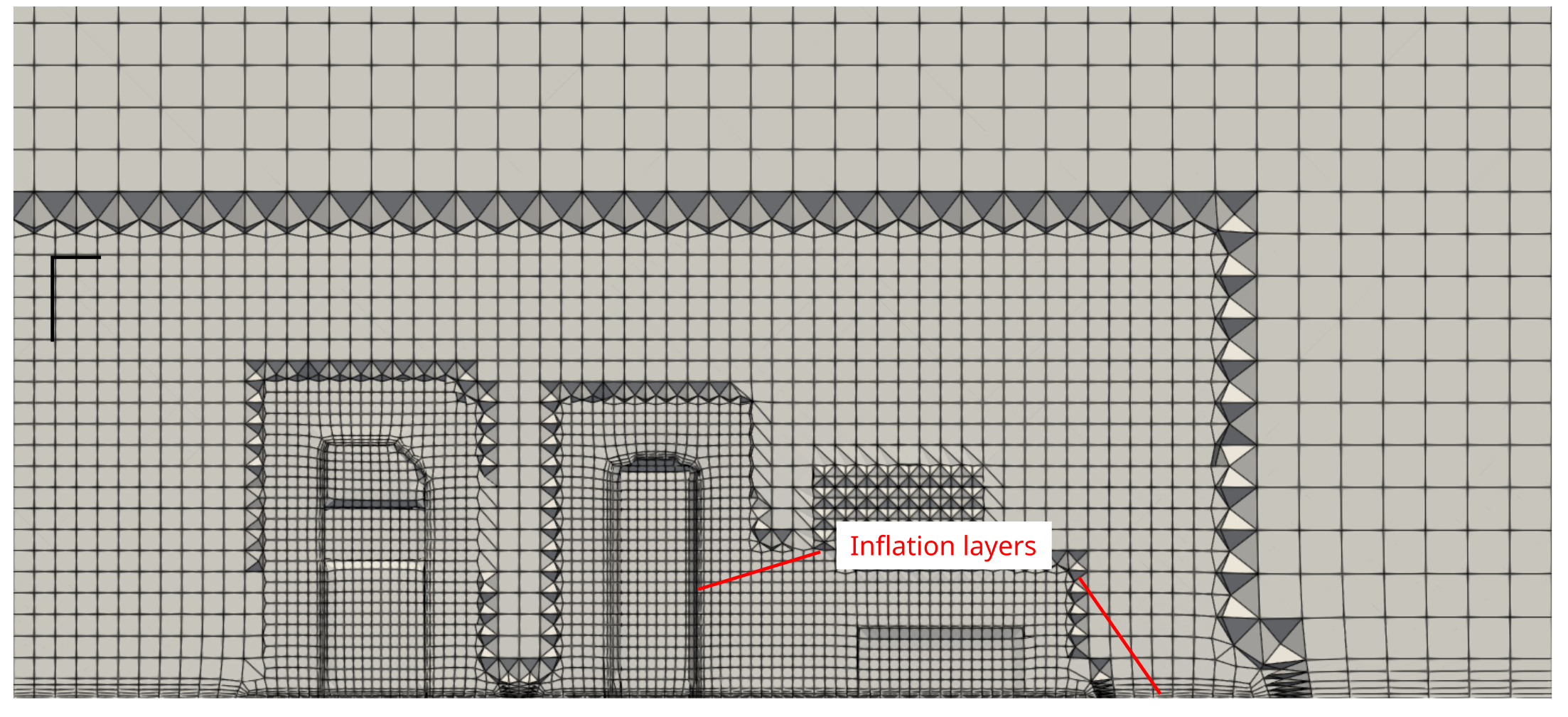
Inflation layer addition
Although being hexahedral-dominant, the mesh still lacks inflation layers to accurately resolve the boundary layer. These can to be added to the patches ground and buildings with the following entry below the region-based refinement in meshDict:
boundaryLayers
{
    patchBoundaryLayers
    {
        buildings
        {
            nLayers           3;

            thicknessRatio    1.3;
        }
        ground
        {
            nLayers           5;

            thicknessRatio    1.3;
        }
    }
}
This setting can be summarized as follows:
boundaryLayersis the keyword forcartesianMeshto add inflation layers.patchBoundaryLayerscollects all specified patches and their individual settings for inflation layers.nLayersis the number of inflation layers added.thicknessRatiois the growth ratio between two consequitive inflation layers.
cartesianMeshautomatically sets the thickness of the first inflation layer based on cell size and thickness ratio. It can optionally be specified using the entrymaxFirstLayerThickness.
In this case, three and five inflation layers are added to the patch buildings and ground, respectively, both with a growth ratio of 1.3. In order to create the new mesh with the updated meshDict, the cartesianMesh utility has to be executed once again:
cartesianMesh
Once the mesh has been recreated, the visualization in ParaView can be updated by clicking the Refresh button the Properties Panel. This results in the following cross-sectional view of the mesh:
Renaming patches
When using cartesianMesh for mesh generation, all patches by default are of type wall. This is obviously incorrect for the atmosphere patch, which should act like an inlet and outlet. Therefore, the patch type has to be changed. This can be accomplished by adding the following lines below the inflation layer setup within the meshDict as follows:
renameBoundary
{
    newPatchNames
    {
        atmosphere
        {
            type    patch;
            newName atmosphere;
        }
    }
}
This setting can be summarized as follows:
renameBoundaryis the keyword forcartesianMeshchange patch names and types.newPatchNamescollects all specified patches and their individual settings in question for change.typespecifies the new patch type of the specified patch.newNamedefines the new patch name.
In this case, only patch atmosphere will get the new patch type patch suitable for inlet and outlets. The new patch name is equal to the original one as it should not be changed. In order to create the new mesh with the updated meshDict, the cartesianMesh utility has to be executed once again:
cartesianMesh
At this point the mesh generation is complete. The mesh consists of:
- Background mesh with a cell size of 10 m.
- Surface-based refinement at the
buildingspatch - Region-based refinement in the wake of the buildings
- Inflation layers at both the ground and the buildings
- Correct patch type for the atmosphere.
Checking mesh quality
Once the mesh generation is complete, the mesh quality must be checked using the OpenFOAM tool checkMesh. In order to visualize the mesh quality metrics in ParaView, the optional parameter -writeAllFields can be added to the command as follows:
checkMesh -writeAllFields
The most relevant output from checkMesh can be summarized as follows:
- Total cell count of 455804 cells
- A maximum aspect ratio of 12.78
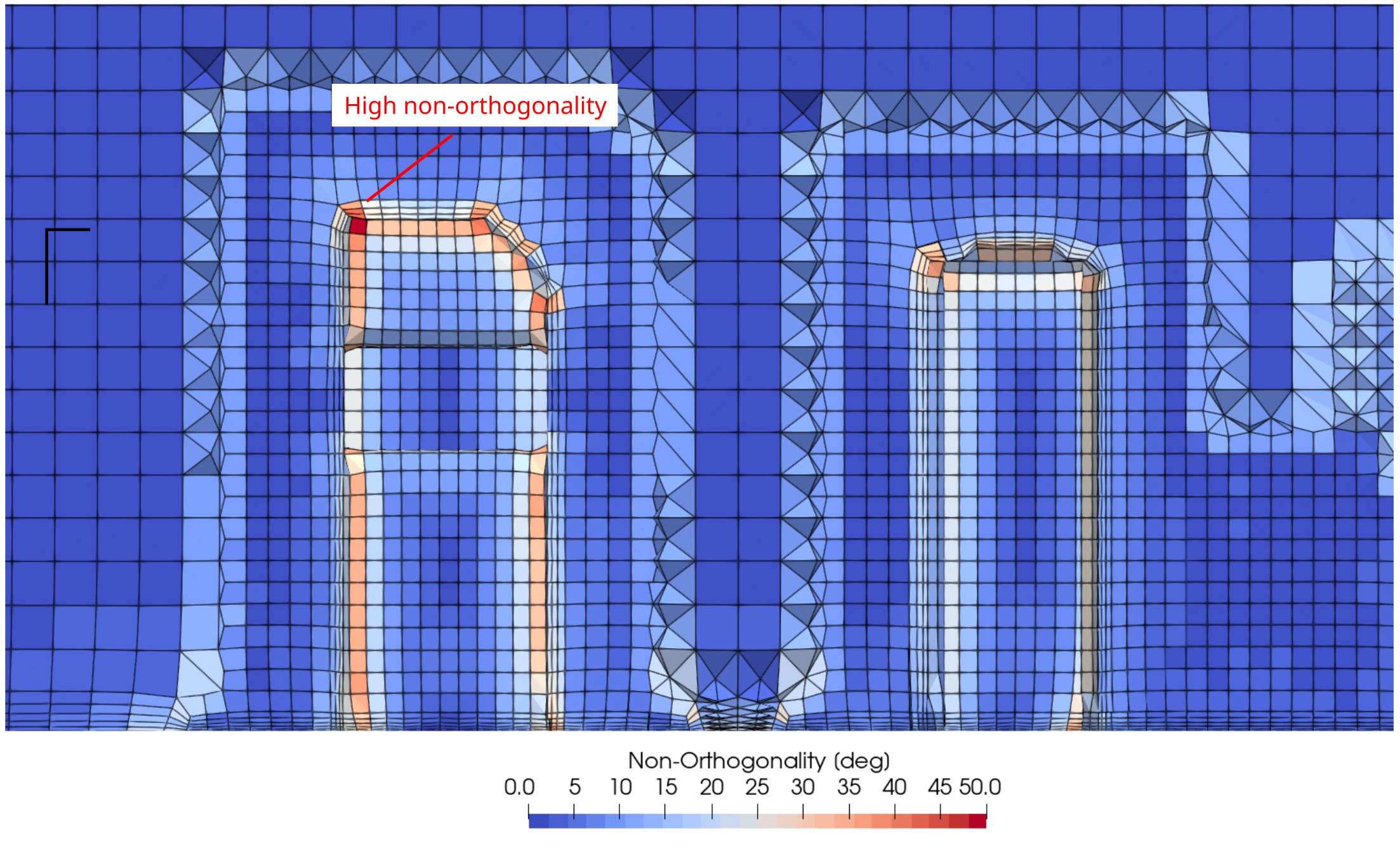
- A mesh non-orthogonality of less than 62.30
- A maximum skewness of 2.48
All these metrics are well below the critical thresholds for OpenFOAM and the mesh can be considered of high quality.
If the mesh quality is not be sufficient,
checkMeshwould highlight the critical metric and the check mesh would fail.
After refreshing the case in ParaView, all important quality metrics are available as field variables for visualization and inspection. For instance, the non-orthogonality (as field named nonOrthoAngle) is highest within the inflation layers around the buildings:
Conclusion
This concludes the second case in the Meshing Tutorial. We have:
- Created a hexahedral-dominant mesh using the OpenFOAM utility
cartesianMeshfor the flow around a group of buildings with:- Surface-based refinement around the buildings
- Region-based refinement in the wake of the buildings
- Inflation layers at both the ground and the buildings
- Correct patch type for the atmosphere.
- Checked the mesh quality with
checkMesh, and - Visualized the mesh with ParaView.